Question 6a
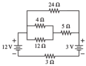
(a) Refer to the circuit shown in Figure 6(a).
i. Calculate the current through the 4 Ω resistor.
ii. Calculate the energy dissipated at the 24 Ω resistor in 12 s.
Solution
Based on the circuit diagram provided, here is the step-by-step solution.
1. Simplify the Circuit
First, let's find the equivalent resistance of the circuit to determine the total current flowing through the main loop.
- Simplify the parallel resistors (
and ):
- Find the resistance of the middle branch:
This combined
- Find the equivalent resistance of the top parallel section:
The top branch (
- Find the total resistance (
):
The equivalent resistance of the parallel section (
2. Calculate Total Current (
The two voltage sources (
Using Ohm's Law (
Part (i): Calculate the current through the
We need to track how the total current of
- Current splitting between the
branch and the middle branch:
Using the Current Divider Rule, the current flowing into the middle branch (
- Current splitting between the
and resistors:
Now, this
Answer (i): The current through the
Part (ii): Calculate the energy dissipated at the
- Find the current through the
resistor ( ):
Since
- Calculate the Power (
) dissipated:
- Calculate the Energy (
):
Answer (ii): The energy dissipated is
Question 6b
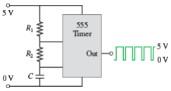
Digital circuits require actions to take place at precise times, so they are controlled by a clock that generates a steady sequence of rectangular voltage pulses. One of the most widely used integrated circuits for creating clock pulses is the 555 timer. Figure 6(b) shows how the timer’s output pulses, oscillating between 0 V and 5 V, are controlled with two resistors and a capacitor.
The manufacturer specifies that the time the clock output spends in the high (5 V) state is
and the time spent in the low (0 V) state is
You need to design a clock that oscillates at 10 MHz (i.e., each cycle is
Solutions
Based on the problem statement and the circuit formulas provided, here is the step-by-step solution to find the values of
1. Identify the Known Variables
First, we need to break down the frequency and duty cycle into specific time values.
- Frequency (
): - Total Period (
): The time for one complete cycle.
-
Duty Cycle: The system spends 80% of the time in the high state.
-
Time High (
): -
Time Low (
): The remaining 20%.
-
-
Capacitance (
): -
Constant:
2. Calculate
We start with
Formula:
Rearrange to solve for
Substitute the values:
3. Calculate
Now that we know
Formula:
Rearrange to solve for
Substitute the values:
Solve for
Final Answer
To achieve a 10 MHz clock with an 80% duty cycle using a 500 pF capacitor: