Question 1
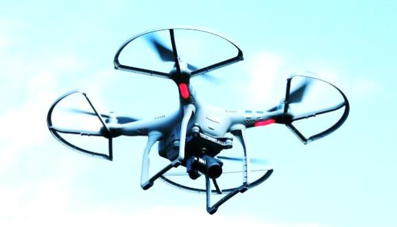
Many devices, such as mobile phones and drones, use Li-ion batteries as storage for electric energy. For a particular battery used for drone flights, the maximum charge that can be stored in one full charge is listed as 6000 mAh (milli-ampere hour). The operating voltage is given as 15.2 V.
i. Determine this maximum charge in Coulomb (C).
ii. In the quadcopter shown, if the four motors are drawing total energy at a constant rate of 120 W at the operating voltage given above, determine the current that is drawn from the battery. Determine how long (in minutes) a battery at full charge can last if it is operating at this current.
iii. The air mass
where the density of air
when the quadcopter is just hovering. If a motor is drawing
Solutions
The problem involves calculating charge, current, power, flight time, and the forces/energy related to the drone's propellers. Let's tackle these one by one.
i. Maximum Charge in Coulombs
The maximum charge is given as
Step 1: Convert milli-ampere (
Step 2: Convert hour (
Since there are
The maximum charge stored in the battery is
ii. Current, Power, and Flight Time
Here, we're using the relationships between Power (
1. Determine the Current Drawn
The total power drawn by the four motors is given as
We can solve for the current (
The total current drawn from the battery is approximately
2. Determine the Battery Duration
The fundamental relationship between Charge (
We'll use the charge in Ampere-hours (
- Charge capacity:
- Current:
3. Convert Time to Minutes
Since there are
The battery can last for approximately
iii. Air Velocity and Upward Force
This part delves into the mechanical power and thrust generated by a single propeller. When the drone is hovering, the total upward force (thrust) from the four propellers must equal the weight of the drone.
1. Determine
The motor draws
The problem provides the formula for this kinetic energy per second (Power
We can now solve for
Plugging in the known values:
Taking the cube root:
The downward velocity of the air due to one propeller is approximately
2. Determine the Upward Force (Thrust)
The upward force, or Thrust (
Since the velocity
We have the expression for
Plugging in the known values:
The upward force (thrust) acting on each propeller blade is approximately
Question 2
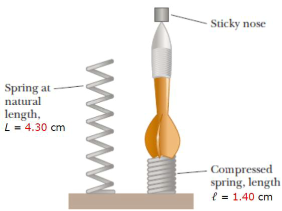
A dart with a sticky nose has a total mass of
i. Determine the maximum height (in m) of the dart with sticky nose from the ground. You can ignore the effects of air resistance and assume that the spring is massless.
ii. Provide one suggestion so that the answer in part (i) will be larger.
iii. If air resistance
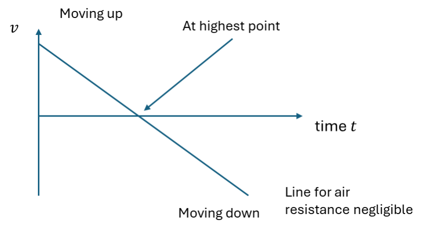
iv. The graph below indicates how the vertical velocity of the dart will change with time just after it loses contact with the spring if air resistance is negligible. Without doing any calculations, sketch on the same axes to show how the velocity will vary if air resistance is not negligible. Label your line “N”.
Solutions
This is a classic problem where potential energy stored in the spring is converted into kinetic energy, and then into gravitational potential energy.
Part i: Maximum Height of the Dart
We can solve this problem by applying the principle of conservation of mechanical energy. We'll consider the system at two key points:
- Initial State (A): The dart is at rest on the fully compressed spring.
- Final State (B): The dart is at its maximum height and is momentarily at rest.
The total mechanical energy
The energy at any point consists of:
- Elastic Potential Energy (
): Stored in the spring, . - Gravitational Potential Energy (
): Due to height, . - Kinetic Energy (
): Due to motion, .
1. Identify Given Parameters and Calculate Spring Compression
First, let's gather and convert our given values to standard SI units (meters and kilograms):
- Mass of the dart,
- Spring constant,
- Natural length of the spring,
- Compressed length of the spring,
The compression distance
2. Energy at the Initial State (A)
Let's set the lowest point of the dart (when the spring is fully compressed) as the reference level for gravitational potential energy, so
- Kinetic Energy (
): The dart is initially at rest, so . - Gravitational Potential Energy (
): At the reference level, . - Elastic Potential Energy (
): The spring is compressed by .
The total initial energy is:
3. Energy at the Final State (B)
At the maximum height
- Kinetic Energy (
): The dart is momentarily at rest at its maximum height, so . - Elastic Potential Energy (
): The spring is now fully uncompressed (at its natural length), so . - Gravitational Potential Energy (
): The dart is at the maximum height .
The total final energy is:
4. Apply Conservation of Energy
Set the initial energy equal to the final energy:
Now, solve for the maximum height
5. Calculation
Substitute the values into the equation:
First, calculate the numerator (initial elastic potential energy):
Next, calculate the denominator (
Finally, calculate
Rounding to three significant figures (based on the given values):
The maximum height of the dart from the ground is
Part ii: Suggestion to Increase the Maximum Height
The equation for the maximum height
To increase the maximum height
Suggestion: Decrease the mass (
- A lighter dart will have less gravitational potential energy stored for the same amount of initial spring energy, allowing it to reach a greater height. This is an easy modification to the dart itself.
Other valid suggestions would be:
- Increase the spring constant (
): Use a stiffer spring. - Increase the compression distance (
): Compress the spring further if possible (the current problem states it's pressed until the coils all press together).
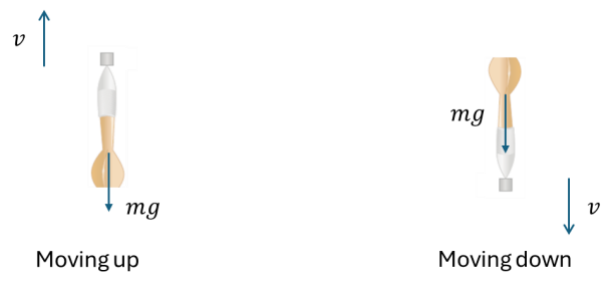
Part iii: Sketching Air Resistance Arrows (
That's an excellent follow-up question! Bringing in air resistance (a non-conservative force) significantly changes the dynamics and requires us to think carefully about the forces acting on the dart.
The key principle here is that air resistance (or drag force) always opposes the direction of motion. Since the air resistance
Here is the sketch with the two arrows labeled
| Motion | Direction of Velocity (v) | Direction of Air Resistance (FR) |
|---|---|---|
| Dart Moving Up | Upward ( |
Downward ( |
| Dart Moving Down | Downward ( |
Upward ( |
Explanation of the Arrows
- Dart Moving Up (Ascending):
- The dart is moving upward.
- The air molecules are pushing against the sticky nose and body of the dart to slow it down.
- Therefore, the air resistance force (
) is directed downward, acting against the velocity.
- Dart Moving Down (Descending):
- The dart is moving downward (after reaching its maximum height).
- The air molecules are again pushing against the dart to slow it down.
- Therefore, the air resistance force (
) is directed upward, acting against the velocity.
Impact on Maximum Height
Just a quick side note: If we included this non-negligible air resistance in the energy calculation from part (i), the maximum height would be less than
Part iv: Velocity-Time Graph with Air Resistance
That's an excellent conceptual question! It challenges us to think about how a non-conservative force like air resistance alters the idealized motion we typically study first.
The straight line on the graph represents the motion under negligible air resistance. This motion is governed solely by gravity, resulting in a constant downward acceleration of
When air resistance (
Here is a sketch of the velocity-time graph with the new line labeled "N":
Key Features of the New Line (N)
The line "N" must show a continuously changing (non-constant) slope, which means the line will be a curve instead of a straight line.
-
Motion Upward (
): - The forces acting on the dart are gravity (
, down) and air resistance ( , down). - The net downward force is
. - Since
is a downward force, the total downward force is greater than just gravity. - Therefore, the downward acceleration (
) is greater than (the slope is more negative). - As the dart slows down (
decreases), decreases, so the magnitude of the slope also decreases slightly (becomes less negative) until the peak. The line starts steeper than the straight line.
- The forces acting on the dart are gravity (
-
At Maximum Height (
): - Air resistance
is proportional to velocity , so when . - The acceleration is momentarily
. - The curve must cross the horizontal axis with the same slope as the ideal straight line.
- Air resistance
-
Motion Downward (
): - The forces acting on the dart are gravity (
, down) and air resistance ( , up). - The net downward force is
. - Since
is an upward force, the total downward force is less than just gravity. - Therefore, the downward acceleration is less than
(the slope is less negative). - The curve is flatter than the straight line. As the dart accelerates downward,
increases (becomes more negative), increases, and the slope continues to decrease in magnitude, leveling off toward a terminal velocity (where ).
- The forces acting on the dart are gravity (
In summary, the curve "N" starts steeper, momentarily matches the slope of the straight line at
Question 3
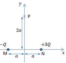
As shown in the figure below, two charges
i. Determine the electric field (in vector form) at point
ii. If a charge
iii. Consider the two charges and the Gaussian surfaces (sphere of radius
Solutions
Before we dive in, let's quickly review the setup from the figure:
- Charge 1:
at point with coordinates . - Charge 2:
at point with coordinates . - The observation point is
with coordinates .
The constants we'll need are:
i. Determine the Electric Field (Vector Form) at Point
The electric field
The formula for the electric field due to a point charge is:
where
Step 1: Determine the distance
The coordinates are
The distance from
The distance from
The distances are the same!
Step 2: Calculate the magnitude of
Let's use the given values:
Magnitude of
Magnitude of
Step 3: Determine the vector components
The electric fields
Let
From the geometry:
Vector
The vector points in the
Vector
The vector points in the
Step 4: Sum the components to find
The Electric Field in Vector Form:
Alternatively, using the numerical approximation:
ii. Calculate the Potential Energy of Charge
The electric potential energy (
where
Step 1: Calculate the Electric Potential
The potential
Note that charge signs are included in the potential calculation, and the result is a scalar.
Since
Plugging in the values:
Using the exact form:
Step 2: Calculate the Potential Energy
The charge being placed at
The Potential Energy is:
Alternatively, using the numerical approximation:
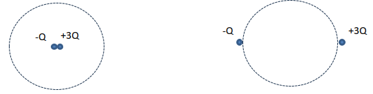
iii. Determine the total electric flux through the Gaussian surfaces
The Underlying Principle: Gauss's Law
Gauss's Law states that the total electric flux (
The mathematical expression is:
Where
The key takeaway is that the size and shape of the Gaussian surface, and the exact positions of the charges outside the surface, do not affect the total flux. Only the net charge inside the surface matters.
The given value is
Case A: Both Charges are at the Center of the Sphere
In Case A (left image), the Gaussian sphere encloses both the charge
Step 1: Calculate the Net Enclosed Charge (
Substituting the value of
Step 2: Calculate the Total Electric Flux (
Using Gauss's Law:
Case B: Both Charges are Just Outside the Sphere
In Case B (right image), both the charge
Step 1: Calculate the Net Enclosed Charge (
Since both charges are outside the closed Gaussian surface, the net charge enclosed by the surface is zero.
Step 2: Calculate the Total Electric Flux (
Using Gauss's Law:
The total electric flux through the surface is zero. (Note: The electric field
Summary of Results
| Case | Net Enclosed Charge (Qenclosed) | Total Electric Flux (ΦE) |
|---|---|---|
| A | ||
| B |
Note on Understanding the Concept
This problem beautifully illustrates the power of Gauss's Law. It tells us that we don't need to know the complex electric field pattern on the surface to find the total flux.
Think of electric flux like the amount of water flowing through a fishing net (your Gaussian surface).
- Case A: If you put a water source (
) and a water sink ( ) inside the net, the net flow through the surface is units out. The net enclosed charge is . - Case B: If the water source and sink are outside the net, the water field lines (electric field lines) must both enter and exit the net. For every line that enters, one eventually leaves, so the net flow through the net is zero. The net enclosed charge is
.
Do you feel confident with the distinction between the total electric field and the total electric flux, especially when charges are outside the Gaussian surface?